2-159
TM 9-2815-237-34
2-41. ENGINE ASSEMBLY FROM SUBASSEMBLIES (Cont’d)
c. Pistons and Connecting Rods
1.
2.
3.
4.
5.
6.
7.
8.
Rotate cylinder block (6) approximately 90°.
NOTE
Measure outside diameter of crankshaft rod bearing journals to
determine what thickness connecting rod bearings to install.
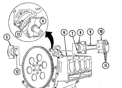
Check identification number on side of connecting rod (9) and install upper rod bearing half (7)
in connecting rod (9) and lower rod bearing half (12) in corresponding rod cap (5).
Rotate crankshaft (4) so rod journal (13) faces outward.
Cover connecting rod bolts (8) with 3/8-in. inside diameter rubber hose.
Apply OE/HDO to piston rings (11) and piston (10).
NOTE
Make sure all ring gaps are staggered so they are not in line with
each other or piston pin.
Compress piston rings (11) with ring compressor.
NOTE
l Depression on top of piston must be assembled toward outside
of engine.
l Starting from front of cylinder block, cylinders 1, 3, 5, and 7 are
on left side and cylinders 2, 4, 6, and 8 are on right side.
l For remaining pistons, rotate crankshaft so rod journal faces
outward.
Check identification number on side of connecting rod (9) and install piston (10) and connecting
rod (9) into corresponding cylinder.
Tap piston (10) into cylinder until connecting rod (9) seats on crankshaft (4) and remove
rubber hoses.
|
|


