TM 9--2815--247--34
0037 00--1
FUEL INJECTOR TUBES, BRACKETS, AND ASSOCIATED PARTS
REPLACEMENT
0037 00
THIS WORK PACKAGE COVERS:
Removal, Cleaning, Inspection, Installation
INITIAL SETUP:
Tools
General mechanic’s tool kit (item 19, WP 0103 00)
Crowfoot attachment (item 11, WP 0103 00)
Bending tool (2) (item 6, WP 0104 00)
Plug gauge set (item 69, WP 0103 00)
Spacer sleeve (2) (item 41, WP 0103 00)
Torque wrench (item 50, WP 0103 00)
Materials/Parts
Self--locking nuts (54) (item 49, WP 0102 00)
Self--locking bolts (2) (item 4, WP 0102 00)
Self--locking nut (item 42, WP 0102 00)
Self--locking nuts (12) (item 57, WP 0102 00)
Lubricant (item 12, WP 0100 00)
Lubricant (item 14, WP 0100 00)
Equipment Conditions
Engine level on flat surface (WP 0031 00)
Engine cleaned and drained
(TM 9--2350--292--20)
Top housing assembly
removed (TM 9--2350--292--20)
References:
TM 9--2350--292--20
Removal
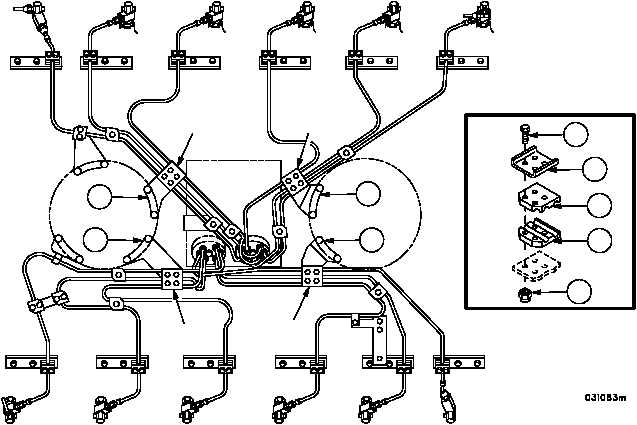
1. Remove 16 bolts (1), 16 self--locking nuts (2), four retaining straps (3), and eight fairlead halves (4) (DETAIL A)
from double--angle brackets (5, 6, 7, and 8). Discard self--locking nuts.
Figure 36
FLYWHEEL
END
DAMPER
END
RIGHT BANK
LEFT BANK
A
A
A
A
A
1
2
3
4
4
7
8
6
5
|
|


