|
|
|
|

|
TM 9--2815--247--34
0054 00--5
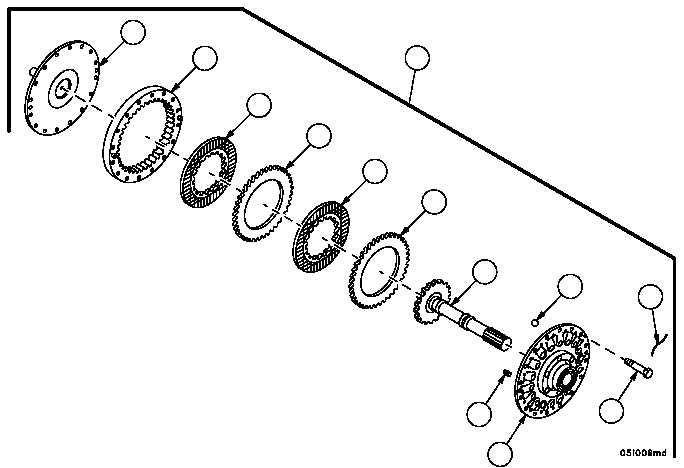
FAN DRIVE CLUTCH ASSEMBLY AND ASSOCIATED PARTS REPAIR --
CONTINUED
0054 00
Disassembly -- Continued
3. Cut and remove locking wire (20) from 16 machine bolts (21). Discard locking wire.
4. Remove 14 of the 16 machine bolts (21) securing fan drive hub assembly (22) to flange (23). Leave two opposite-
ly positioned bolts (21) in place.
5. Place friction clutch (15) in machinist’s vice with short end of shaft on bottom.
6. Alternately loosen two bolts (21) until flange (23) comes off fan drive hub assembly (22).
7. Remove flange (23) and housing assembly (24) from fan drive hub assembly (22).
8. Remove three springs (25) and six ball bearings (26) from fan drive hub assembly (22).
9. Remove two clutch disks (27) and two clutch disks (28) from housing assembly (24).
10. Separate housing assembly (24) from flange (23).
11. Remove shaft assembly (29) from fan drive hub assembly (22).
Figure 55
20
21
22
23
24
15
27
27
28
28
29
25
26
|
|
|
|
|
Privacy Statement -
Copyright Information. -
Contact Us