TM 9--2815--247--34
0059 00--9
CYLINDER HEAD ASSEMBLY REPLACEMENT -- CONTINUED
0059 00
Installation -- Continued
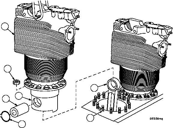
12. Remove piston pin (13) from piston (11).
WARNING
13. Lift cylinder head assembly (1) with piston installed and slide into position over connecting rod (14), having a help-
er insert piston pin (13) through connecting rod (14) and piston (11).
WARNING
NOTE
Retaining rings must be installed with flat side facing out-
ward.
14. Have helper install two new retaining rings (12) in grooves at each end of piston (11).
15. Lower cylinder head assembly (1) over piston (11) and onto crankcase studs (5), having helper temporarily secure
with two base nuts (4).
14
13
11
12
Figure 5
5
1
4
|
|