TM 9--2815--247--34
0070 00--3
CONNECTING ROD ASSEMBLY AND ASSOCIATED PARTS REPAIR --
CONTINUED
0070 00
Removal -- Continued
CAUTION
Connecting rods and caps are matched sets and must be
kept together for inspection and assembly. If subsequent
inspection indicates the bearings are reusable, they must
be reassembled in their normal positions. Failure to com-
ply will result in premature failure.
NOTE
Connecting rods and caps are stamped with location
number on the side of one of the bosses. For example,
“1R” would identify connecting rod and cap for No. 1 cyl-
inder on the right bank. The identifying serial numbers
are located on the side opposite the cylinder location
numbers.
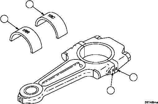
3. Mark the two bearings (4 and 5) with a grease pencil or suitable marker to indicate their locations. For example,
the connecting rod bearing half (4) for cylinder “1R” should be marked “1RR” and the cap bearing half (5) should
be marked “1RC”.
4. If the connecting rod (7) or cap (8) markings are obliterated, restamp connecting rods and caps so that they can
be installed in their original positions.
Figure 8
5
4
7
8
|
|