TM 9--2815--247--34
0081 00--2
OIL PRESSURE COMPARTMENT BAFFLE, OIL PUMP, AND ASSOCIATED
PARTS REPLACEMENT -- CONTINUED
0081 00
Removal -- Continued
WARNING
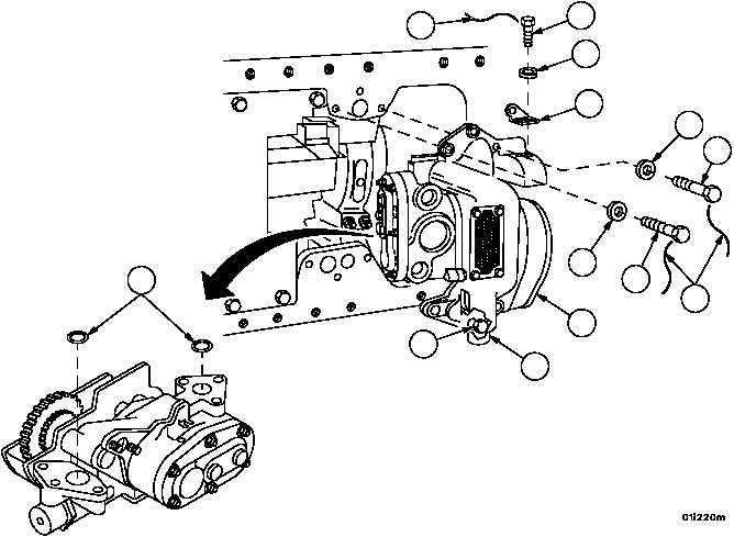
5. Remove non--electrical wire (8) from screws (9, 10, and 11). Discard non--electrical wire.
6. Remove screw (9), flat washer (12), two screws (10), two lockwashers (13), and mounting bracket (14). Discard
lockwashers.
7. Remove four screws (11) and four flat washers (15) from oil pump (6).
NOTE
The screw and flat washer behind the oil pressure relief
valve cap cannot be removed until the oil pump is disas-
sembled.
8. Loosen screw (16) located behind cap (17) and remove oil pump (6).
9. Remove two preformed packings (18). Discard preformed packings.
Figure 18
10
18
13
14
9
12
11
15
6
16
17
8
8
|
|


