|
|
|
|

|
TM 9--2815--247--34
0083 00--3
GENERATOR DRIVE MECHANISM REPAIR -- CONTINUED
0083 00
Removal -- Continued
WARNING
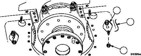
3. Cut and remove locking wire (14) and remove two slotted nuts (15) securing shouldered shaft (16).
Figure 29
16
14
15
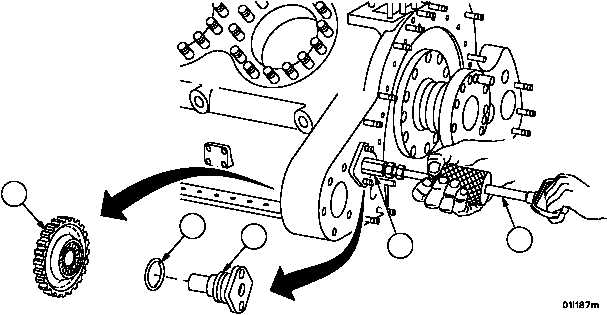
4. Attach mechanical adapter (17) and slide hammer puller (18) to shouldered shaft (16).
5. Support spur gear (19) with a wooden block while using the slide hammer puller (18) to remove shouldered shaft
(16).
6. Remove preformed packing (20). Discard preformed packing.
7. Remove slide hammer puller (18) and mechanical adapter (17) from shouldered shaft (16).
8. If it is necessary to remove spur gear (19) from crankcase, crankshaft must be removed. Refer to WP 0064 00.
Figure 29
18
17
16
20
19
|
|
|
|
|
Privacy Statement -
Copyright Information. -
Contact Us