TM 9--2815--247--34
0083 00--7
GENERATOR DRIVE MECHANISM REPAIR -- CONTINUED
0083 00
Inspection -- Continued
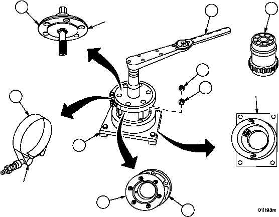
9. Secure generator holding tool (34) to workbench and remove “V” band clamp (35).
10. Remove adapter (36) and plate (37), secured to the tool base (34) with two plain nuts (38) and two lockwashers
(39).
11. Place spur gear slip clutch (21) in tool base (34) with gear teeth meshed with those in the base.
12. Secure adapter (36) and plate (37) to tool base (34) with two plain nuts (38) and two lockwashers (39).
13. Install splined end of generator coupling tool (1) into spur gear slip clutch (21) and secure to generator holding
tool (34) with “V” band clamp (35).
14. Using torque wrench (6) on the generator coupling tool (1), gradually increase the torque to 167 lb--ft (227 NSm).
If slippage occurs below 167 lb--ft (227 NSm), the spur gear slip clutch is defective and must be replaced.
15. Check the torque rotational deflection rate by gradually applying 167 lb--ft (227 NSm) of torque to the generator
coupling tool (1). Note the deflection in degree at 167 lb--ft (227 NSm). If deflection is less than 8°, or greater than
17°, the spur gear slip clutch is defective and must be replaced.
Figure 73
1
BENCH FIXTURE
GENERATOR COUPLING
TOOL
6
35
34
21
38
39
37
36
“V” BAND CLAMP
|
|