TM 9--2815--247--34
0096 00--1
MECHANICAL DRIVE HOUSING AND ASSOCIATED PARTS (FAN TOWER,
DAMPER END) REPAIR
0096 00
THIS WORK PACKAGE COVERS:
Removal, Disassembly, Inspection, Repair, Assembly, Installation
INITIAL SETUP:
Tools and Special Tools
General mechanic’s tool kit (item 19, WP 0103 00)
Lifting tool (item 9, WP 0104 00)
Retaining ring pliers (item 39, WP 0103 00)
Outside micrometer caliper set (item 9, WP 0103 00)
Inside micrometer caliper set (item 10, WP 0103 00)
Telescoping gauge set (item 16, WP 0103 00)
Arbor press (item 2, WP 0103 00)
Torque wrench (item 50, WP 0103 00)
Materials/Parts
Self--locking nuts (4) (item 45, WP 0102 00)
Cotter pins (4) (item 91, WP 0102 00)
Key washer (item 141, WP 0102 00)
Self--locking nuts (9) (item 55, WP 0102 00)
Preformed packing (item 76, WP 0102 00)
Retaining rings (2) (item 120, WP 0102 00)
Retaining rings (2) (item 112, WP 0102 00)
Materials/Parts -- Continued
Wire, nonelectrical (item 22, WP 0100 00)
Sealant (item 21, WP 0100 00)
Pipe plug (item 97, WP 0102 00)
Lubricant (item 12, WP 0102 00)
Pipe plug compound (item 7, WP 0100 00)
Safety goggles (item 28, WP 0100 00)
Equipment Conditions
Engine on maintenance stand (WP 0056 00)
Breather tubes, oil supply hoses, fuel return lines and
fire extinguisher tube removed
(TM 9--2350--292--20)
Fuel metering pump assembly removed
(WP 0039 00)
References
TM 9--2350--292--20
Removal
1. Loosen two hose clamps (1) on two metal tube assemblies (2 and 3).
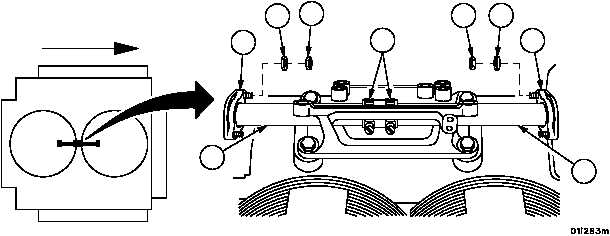
2. Remove four self--locking nuts (4) and four flat washers (5) securing shaft retaining plates (6). Discard self--lock-
ing nuts.
Figure 53
FORWARD
5
4
4
5
3
2
1
6
6
|
|


