TM 9-2815-250-24&P
3-10. ROCKER ARM ASSEMBLIES REPAIR (continued).
3.
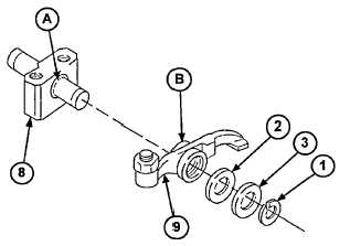
Remove two rocker arms (6 and 9) from rocker arm bracket (8).
NOTE
Remove nuts and adjusting screws only if damaged.
4.
Remove two nuts (4) and adjusting screws (5) from two rocker arms (6 and 9). If damaged, discard nuts and
adjusting screws.
b.
INSTALLATION
NOTE
· There are two rocker arm assemblies on the engine. Repeat steps 1 through 4 to
install both of them.
· If nuts or adjusting screws need to be replaced, do step 1. If not, go to step 2.
1.
Install two new nuts (4) on two new adjusting screws (5). Install two adjusting screws (5) on two rocker arms (6 and
9).
2.
Place two rocker arms (6 and 9) on rocker arm bracket (8) and secure with two new retaining rings (1).
3.
To determine if shims (2 or 3) are needed, use a
feeler gage to measure play between rocker arm
bracket (8) (point A) and inside edge of rocker arm
(6 or 9) (point B). This measurement should be
between 0.004 and 0.008 inch (0.1 mm and 0.2
mm). Remove two retaining rings (1) from rocker
arm bracket (8), and install shims (2 or 3) as
needed to achieve this distance. Reinstall
retaining rings (1) in rocker arm bracket (8).
CAUTION
To ensure adequate lubrication, rocker arm bracket must be installed with the oil
hole on the bottom.
4.
Install rocker arm bracket (8) on two studs (10) and secure with two new self-locking nuts (7). Torque nuts to 17 ft-
lb (23 Nm).
FOLLOW-ON TASKS:
Adjust valves (para 3-18).
Install rocker arm covers and gaskets (para 2-17).
3-39
|
|