TM 9-2815-250-24&P
3-11. CAMSHAFT REPAIR (continued).
5.
Remove governor control lever assembly pin (6) and governor control lever assembly (3) from upper crankcase
(15).
6.
Remove two O-rings (7) from pin (6). Discard O-rings.
7.
Remove camshaft assembly (5) from upper crankcase (15): Position the timing marks on camshaft gear (4) at the
10 o'clock position. Pull camshaft assembly (5) toward you until it stops. Turn camshaft gear (4) until timing marks
are in the 12 o'clock position. Pull camshaft assembly (5) the rest of the way out of upper crankcase (15).
CAUTION
Do not lay camshaft flat on table while it is attached to camshaft gear. Stand
camshaft and camshaft gear assembly on camshaft gear, to prevent warping.
8.
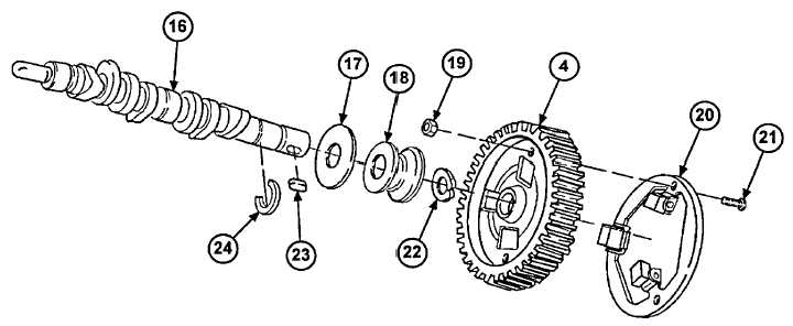
Remove three screws (21) and nuts (19) and mounting plate (20) from camshaft gear (4).
9.
Remove retaining ring (24) from groove on camshaft (16), and slide spacer (18) and washer (17) away from
camshaft gear (4). Discard retaining ring.
10.
Remove camshaft gear (4) and key (23) from camshaft (16).
11.
Remove retaining ring (22) from groove on camshaft (16). Discard retaining ring.
12.
Remove spacer (18) and washer (17) from camshaft (16).
3-41
|
|