ARMY TM 9-2815-252-24
AIR FORCE TO 38G1-92-2
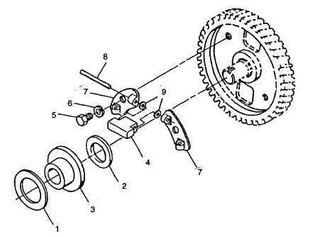
I. Turn camshaft until a weight (4, FIGURE 3-20) is horizontal.
m. Remove capscrew (5) and lockwasher (6) securing each retainer plate (7) to camshaft gear. Remove retainer
plate (7) with weights. Discard lockwasher.
n. Remove pin (8), shims (9), and weights (4) from retainer plate.
o. Repeat steps I through n for other retainer plates and weights.
p. Lightly lubricate pins (8) with engine lubricating oil (MIL-L-2104) and install them and shims (9) in new weights
(4)
q. Install weights (4) and pins (8) with large section of weights facing out.
FIGURE 3-20. Governor Weights
r. Install retainer plates (7) and secure each with a capscrew (5) and new lockwasher (6). Tighten capscrews to
6.5 ft-lbs (8.8 Nm)
s. Ensure all weights (4) move freely.
t. Install two bushings (39, FIGURE 3-19) and thrust collar (38) on governor lever (6).
u. Install two capscrews (35 and 36) and nuts (37) on base plate (34).
v. Position base plate (34) on crankcase and secure with capscrew (33).
w. If removed, install new bushing (32).
x. From outside crankcase, install new preformed packing (31) and speed quadrant (30) into crankcase hole.
y. From inside crankcase install lever (29) on speed quadrant (30) and secure with capscrew (27) and washer
(28).
z. From outside crankcase, position bushing (23), new preformed packing (24) and lever (25) into crankcase
hole.
aa. Install trip lever spring (26) on lever assembly (22).
ab. From inside crankcase, position lever assembly (22), bushing (21), and spring (20) on lever (25) and secure
with capscrew (18) and washer (19).
3-43
|
|