ARMY TM 9-2815-252-24
AIR FORCE TO 38G1-92-2
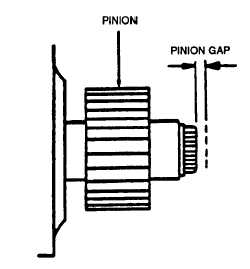
FIGURE 3-26. Checking Pinion Gap
Section X. ENGINE SUBASSEMBLY MAINTENANCE
3-25. CYLINDER COVER.
3-25.1. Removal. Remove two nuts (1, FIGURE 3-27) and preformed packings (2) securing each valve cover (3) to
cylinder head; remove cover (3) and gasket (4). Discard gasket (4) and preformed packings (2).
3-25.2. Inspection.
a. Inspect cover for cracks, dents, or any other damage.
b. Inspect nuts for rounded hex corners or thread damage.
3-25.3. Installation
a. Remove any traces of old gasket from cylinder head and valve covers (3, FIGURE 3-27) mating surfaces.
b. Ensure mating surfaces are clean and dry.
c. Position each valve cover (3) with new gasket (4) on cylinder head and secure with two nuts (1) and new
preformed packings (2). Tighten nuts (1) to 78 in-lbs (8.8 Nm).
3-23. ROCKER LEVER.
3-26.1. Removal.
a. Remove cylinder covers, refer to paragraph 3-25.1.
b. Remove nut (5, FIGURE 3-27) securing rocker lever (6) to cylinder head bolt (7); remove rocker lever.
c. Remove pushrod (9).
d. Repeat steps b and c for remaining rocker levers and pushrods.
e. Do not remove cylinder head bolt (7) and spacer (8) unless damaged or cylinder head is being removed.
3-26.2. Inspect and Measure.
a. Check pushrod (9, FIGURE 3-27) as follows:
(1 ) Lay pushrod on a surface plate.
3-52
|
|


