ARMY TM 9-2815-252-24
AIR FORCE TO 38G1-92-2
g. Three head gaskets (7) are available. Check old gasket for number of identification holes in one corner of
gasket. One hole - 0.053 in. (1.35 mm); 2 holes - 0.058 in. (1.47 mm); and 3 holes - 0.063 in. (1.60 mm)
h. Install a new gasket (7) and cylinder head (6) over guide studs. Ensure that pushrod tubes (8) are properly
aligned with head.
i. Remove cylinder head guide studs.
NOTE
There are three types of cylinder head bolts used. Install them in their proper locations as noted
during removal.
j. Install two bolts (3), two bolts (4), and four washers (5). Refer to FIGURE 3-27 and install four bolts (7) and
spacers (8). Tighten all bolts finger tight.
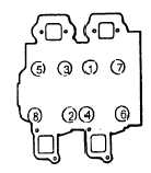
k. Tighten all eight bolts in three stages and in sequence shown in FIGURE 3-31.
(1) First tighten to 6.2 ft-lbs (8.4 Nm).
FIGURE 3-31. Cylinder Head Bolt Tightening Sequence
(2) Second tighten to 38.5 ft-lbs (52.2 Nm).
(3) Final tighten to 66.6 ft-lbs (90.3 Nm).
I. Install rocker levers and Pushrods, refer to paragraph 3-26.3.
m. Install cylinder covers, refer to paragraph 3-25.3.
n. Position lifting eye (2, FIGURE 3-28) on bolts (4) and secure with two nuts (1)
o. Install fuel injectors, refer to paragraph 3-17.4.
p. Install fuel injector pipes, refer to paragraph 3-18.3.
q. Install exhaust manifold, refer to paragraph 3-7.3.
r. Install intake manifold, refer to paragraph 3-3.
3-28. GEAR FND COVFR.
3-28.1. Removal.
a. Insert common screwdriver through flywheel housing into flywheel gear ring. Ensure that it is in position by
attempting to turn flywheel.
b. Remove fan belt, refer to end item maintenance manual.
NOTE
Bolt (1, FIGURE 3-32) has left hand threads.
3-61
|
|