ARMY TM 9-2815-252-24
AIR FORCE TO 38G1-92-2
3-29. CAMSHAFT ASSFMBLY,
3-29.1. Removal.
a. Remove end cover, refer to paragraph 3-28.1.
b. Remove cylinder head, refer to paragraph 3-27.1.
c. Remove fuel injection pumps, refer to paragraph 3-13.1.
d. Remove governor system, refer to paragraph 3-23.1.
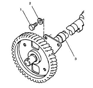
e. Rotate camshaft until large holes in gear line up with two capscrews (1, FIGURE 3-34).
f. Remove two capscrews (1) and lockwashers (2) securing thrust plate to crankcase; remove camshaft (3) from
crankcase keeping it square at all times. Discard lockwashers.
FIGURE 3-34. Camshaft Assembly
CAUTION
No attempt must be made to remove pinion gear from camshaft. Camshaft and gear are supplied
as an assembly.
3-29.2. Inspect and Measure.
a. Examine camshaft bushing for scars or wear.
b. Check camshaft gearwheel and crankshaft pinion teeth for wear.
c. Ensure cams are not chipped or damaged.
d. Check tappets for damage to contact face.
e. Using appropriate measuring devices check components listed in TABLE 3-5 for wear. Replace components
that exceed maximum clearance.
f. Check gear end of shaft for nicks and burrs.
3-64
|
|