ARMY TM 9-2815-252-24
AIR FORCE TO 38G1-92-2
f. Install governor system, refer to paragraph 3-23.4.
g. Install fuel injection pumps, refer to paragraph 3-13.4.
h. Install cylinder head, refer to paragraph 3-27.6.
i. Install end cover, refer to paragraph 3-28.3.
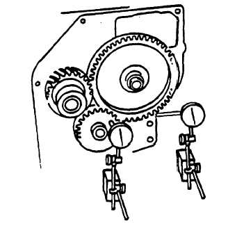
FIGURE 3-35. Measuring Gear Backlash and End Play
3-30. PISTON AND CONNECTING ROD ASSEMBLIES.
3-30.1. Removal.
a. Remove crankcase door, refer to paragraph 3-20.2.1.
b. Remove cylinder head, refer to paragraph 3-27.1.
c. If number one piston is to be removed, unscrew oil pressure relief valve and oil strainer from oil pump.
d. Rotate crankshaft as necessary to gain access to connecting rod bearing cap capscrews (1, FIGURE 3-36).
Warning
To avoid possible Injury, due to sharp edges of machined crankcase face, use a drive socket and
not a wrench.
CAUTION
Number stamped on connecting rod must correspond with number stamped on end cap.
Damage to crankshaft can occur.
e. Remove two capscrews (1), connecting rod (3), and bearing cap (2).
f. If damaged or worn, remove bearing halves (4).
g. Carefully scrape any build up of carbon from top of cylinder bore.
h. Rotate crankshaft until piston is at TDC.
3-66
|
|


