|
|
|
|

|
ARMY TM 9-2815-253-24
AIR FORCE TO 38G1-93-2
MARINE CORPS TM 2815-24/3
t.
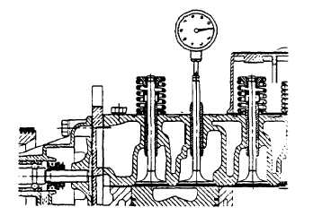
Mount a dial indicator. Refer to FIGURE 3-10 to cylinder head to check intake valve drop. Carefully turn engine
a small amount either side of TDC and dial indicator can be zeroed at TDC.
FIGURE 3-10. Checking Piston Drop
g.
Measure piston drop. Engine should then be rotated opposite normal crankshaft rotation (counterclockwise as
viewed from fan end) to approximately 0.01 in. (0.2544 mm) drop beyond specified piston drop of 0.99 in.
(2.519 mm). Then rotate in direction of normal crankshaft rotation until specified piston drop is reached. It is
important that specified piston drop be approached in direction of normal crankshaft rotation.
NOTE
It may be necessary to push down on valve stem to overcome friction of stem seal and maintain
contact of valve head to piston crown.
NOTE
Ensure top face of crankcase is clean.
h.
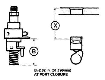
Using a depth gage, measure distance (X) from top face of crankcase to top of fuel pump tappet cap. Refer to
FIGURE 3-11. Subtract dimension (X) from dimension (B) 2.02 in. (51.196 mm) to obtain required thickness of
shim pack to be installed between fuel injection pump plate and crankcase.
FIGURE 3-11. Fuel Injection Pump Dimensions
3-24
|
|
|
|
 |
Privacy Statement -
Copyright Information. -
Contact Us


