|
|
|
|

|
ARMY TM 9-2815-253-24
AIR FORCE TO 38G1-93-2
MARINE CORPS TM 2815-24/3
NOTE
Bolt (1) has left-hand threads.
j.
Install crankshaft pulley (2) on crankshaft and secure with bolt (1). Tighten bolt (1) to 221 ft-lbs (300 Nm).
k.
Remove screwdriver.
I.
Install fan belt. Refer to end item maintenance manual.
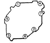
FIGURE 3-33. Gear End Cover Capscrew Tightening Sequence
3-29. CAMSHAFT ASSEMBLY.
3-29.1. Removal.
a.
Remove end cover. Refer to paragraph 3-28.1.
b.
Remove cylinder head. Refer to paragraph 3-27.1.
c.
Remove fuel injection pumps. Refer to paragraph 3-13.1.
d.
Remove governor system. Refer to paragraph 3-23.1.
e.
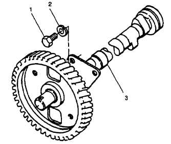
Rotate camshaft until large holes in gear line up with two capscrews (1, FIGURE 3-34).
f.
Remove two capscrews (1) and lockwashers (2) securing thrust plate to crankcase; remove camshaft (3) from
crankcase keeping it square at all times. Discard lockwashers.
FIGURE 3-34. Camshaft Assembly
3-58
|
|
|
|
|
Privacy Statement -
Copyright Information. -
Contact Us