ARMY TM 9-2815-254-24
AIR FORCE TO 38G1-94-2
(6) Remove bearing cap.
(7) Compare width of bearing gage attached to either crankshaft or bearing against scale printed on bearing
gage container.
(8) Standard clearance is 0.0007 to 0.0025 in. (0.018 to 0.065 mm), with a limit of 0.0047 in. (0.12 mm).
(9) If measured clearance exceeds limit, perform clearance check in accordance with step g.
3-28.4. Assembly.
N O T E
Crankshaft gear timing mark ‘X-X must face out.
a.
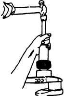
Install key (17, FlGURE 3-77) on crankshaft and using gear installer (320908) install gear (16) on crankshaft,
refer to FlGURE 3-92.
b.
Install deflector (15, FlGURE 3-77) on crankshaft.
c.
Clamp connecting rod in a soft-jawed vice.
FIGURE 3-92. Crankshaft Gear Installation
3-141
|
|