ARMY TM 9-2815-254-24
AIR FORCE TO 38G1-94-2
k.
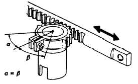
Push control rack (39) fully toward drive side and then pull fully in opposite direction. Ensure that sleeve pinion
(30) moves through same angle from control rack’scenter position when control rack is pushed or pulled, refer
to FIGURE 3-28.
FIGURE 3-28. Checking Sleeve Pinion Movement
l.
Install upper spring seat (28) and spring (27) on plunger barrel (37) through bottom plug holes.
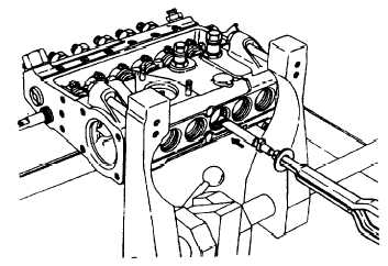
m. Dip plunger (24) in clean diesel fuel and hold it with mechanical fingers. Insert plunger with lower spring seat
(25) into barrel (37) with helix facing upward and manufacturer’s mark facing downward, refer to FIGURE
3-29.
FIGURE 3-29. Inserting Plunger
3-51
|
|