ARMY TM 9-2815-255-24
AIR FORCE TO 38G1-95-2
MARINE CORPS TM 2815-24/4
NOTE
If engine front plate must be replaced, refer to paragraph 3-43.4. for transferring timing mark. No
timing mark will be found on new front plate, a mark must be established and scribed.
a.
Using center bolt on harmonic balancer, rotate crankshaft until No. 1 piston is at TDC on compression stroke.
Insert timing pin (JDE-81-4).
b.
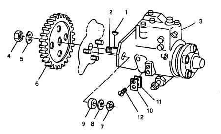
Make sure woodruff key (1, FIGURE 3-91) is installed in pump shaft (2) and that it is not loose in shaft.
CAUTION
Do not drop shaft nut (4), or washer (5) into timing gear area while Installing Injection pump.
c.
Slide injection pump (3) onto mounting studs while inserting pump shaft into drive gear (6). Install lockwasher (5)
and drive gear-to-shaft nut (4) on pump shaft (2).
d.
Install three nuts (7) new lockwashers (8), and washers (9). Tighten finger tight only at this time.
FIGURE 3-91. Fuel Injection Pump Installation
e.
Tighten drive gear-to-shaft nut (4) to 45 ft-lbs (60 Nm). Install access cover plate using a new gasket.
f.
First, pivot pump housing away from cylinder block as far as slots will allow. Then, pivot it back again, but only
far enough to align timing mark on the pump flange exactly with timing mark on the cylinder block front plate.
This is to take up any possible gear backlash.
g.
Tighten three mounting nuts (7) securing pump to front plate to 20 ft-lbs (27 Nm).
h.
Remove all caps and connect injection pump pressure lines. Beginning with outlet for one fuel injection line (12,
FIGURE 3-41 ) and continue around the pump head in counterclockwise direction, attaching lines in same order
as engine firing (1-3-4-2).
Change 2 3-121
|
|