|
|
|
|

|
ARMY TM 9-2815-255-24
AIR FORCE TO 38G1-95-2
MARINE CORPS TM 2815-24/4
(4)
The difference between the two measurements in steps (2) and (3) is distance liner is out of round at
bottom.
(5)
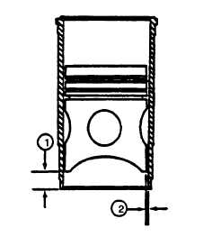
Remove piston from liner. Put piston in liner upside down with piston FRONT and liner FRONT aligned.
Move piston so bottom edge of piston skirt is 1.00 inch (25.4 mm) (1) below top of liner. Use a feeler gage
to measure clearance (2) between piston skirt and liner at 90 degrees to piston pin bore. Record the
measured clearance.
FIGURE 3-134. Measuring Piston to Liner Clearance
(6)
Turn piston 90 degrees in liner. Use a feeler gage to measure clearance between piston skirt and liner 90
degrees to piston pin bore. Record the measured clearance.
(7)
The difference between the two measurements in steps (5) and (6) is the amount the liner is out of round at
the top of the liner.
(8)
If liner is out of round more than 0.002 inch (0.05 mm) at top or bottom, install a new piston and liner set.
(9)
Find difference between clearance measured in step (2) and clearance measured in step (5). This is the
amount the liner is tapered.
(10)
If liner is tapered more than 0.002 inch (0.05 mm) install a new piston and liner set.
3-47.2. Connecting Rod.
a.
Check bearing to journal oil clearance as follows using bearing gage (PLASTIGAGEPR1).
CAUTION
Never use new connecting rod caps crews when checking rod bearing ID. Use new capscrews
only for final assembly of connecting rods.
CAUTION
Using pneumatic wrenches may cause thread damage.
3-194
|
|
|
|
 |
Privacy Statement -
Copyright Information. -
Contact Us


