ARMY TM 9-2815-255-24
AIR FORCE TO 38G1-95-2
MARINE CORPS TM 2815-24/4
(5)
Initially tighten capscrews to 41 ft-lb (56 Nm). Tighten screws an additional 90 to 100 degrees, refer to
paragraph 3-50.3.i for Torque-Turn Method for proper torque.
(6)
Using an inside micrometer, measure rod bore at center of bore and record measurements as follows:
(a)
At right angle to rod/cap joint.
(b)
At 45 degrees left of measurement step (a).
(c)
At 45 degrees right of measurement step (a).
(d)
Rod bore ID should be 2.900 to 2.901 inches (73.66 to 73.69 mm).
(7)
Compare measurements. If difference between greatest and least measurement is more than 0.0015
inch(0.038 mm), rod and cap are out of round. Replace both connecting rod and cap.
d.
Inspect piston pins and bushings as follows:
(1)
Visually inspect piston pin for general overall condition. Pin must be replaced if it shows signs of fretting.
CAUTION
Piston pin has a highly polished surface. Do not attempt to polish or refinish.
(2)
Using outside micrometer, measure piston pin OD. Replace if not within 1.624 to 1.62.5 inches (41.27 to
41.28 mm).
(3)
Inspect piston pin bushing for damage or excessive wear. Lubrication hole must be open.
(4)
Compare pin bushing ID with pin OD for specified oil clearance.
(5)
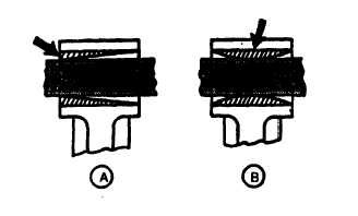
Insert pin from either side of rod bushing. If pin is free on one end, but tight on other, bore could be
tapered (A, FIGURE 3-135). If pin, enters freely from both sides, but is tight in center, bore is bell mouthed
(B). Pin-to-bushing clearance should be 0.0008 to 0.0024 inch (0.02 to 0.06 mm), with a maximum of
0.004 inch (0.10 mm).
FIGURE 3-135. Checking Piston Pin Bushing
e.
Replace connecting rod bushing.
(1)
Using driver (JD-286), remove connecting rod bushing (12, FIGURE 3-124).
(2)
Clean bore of rod with medium grit polishing cloth.
(3)
Inspect rod bore for cracks. Ensure lube oil hole is open.
NOTE
If bushing has spun or it rod bore diameter is not within specifications, replace connecting rod.
3-196
|
|


