ARMY TM 9-2815-255-24
AIR FORCE TO 38G1-95-2
MARINE CORPS TM 2815-24/4
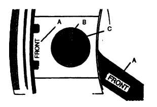
FIGURE 3-144. Assembled Piston, Pin, and Connecting Rod
(3)
Insert piston pin (B) into piston pin bore. Install new piston pin retaining rings (C) with sharp edge of ring
facing away from piston pin. Check to be sure retaining rings are seated in grooves of piston pin bore.
CAUTION
Always refer to manufacturer's specifications for ring Identification markings and locations
before Installation. Failure to Install rings In the proper locations will result in equipment
damage.
b.
Install new piston rings (8, FIGURE 3-124) as follows:
(1)
Using piston ring expander, install oil ring expander in bottom ring groove. Position end gap over either
end of piston pin.
(2)
Install oil control ring in bottom ring groove over ring expander. Install with end gap on opposite side of
piston from ring expander gap.
NOTE
A dye stain is added to rectangular and keystone compression rings for added identification.
(3)
Rectangular compression ring (FIGURE 3-145) is marked with two depressions or with word TOP to
identify top side of ring. Install rectangular compression ring in center ring groove with mark toward top of
piston.
3-204
|
|