ARMY TM 9-2815-255-24
AIR FORCE TO 38G1-95-2
MARINE CORPS TM 2815-24/4
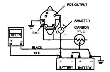
FIGURE 3-13. Battery Charging Alternator Test Circuit
NOTE
Carbon pile and ammeter must be capable of handling the alternator rated output.
(3)
Starting with the carbon pile off, slowly increase load while observing ammeter and maintaining 5000 rpm.
Increase load until an output voltage of 27.0 to 29.0 VDC is achieved. Record the output current at this
point. Acceptable current is 38 amperes at 70 to 80°F (21.1 to 26.70C).
3-11.7. Installation.
a.
If removed, install jumper wire (18, FIGURE 3-5) and nuts (19).
b.
If removed, position mounting brackets (15 and 17) on timing gear cover mounting holes; secure with two
capscrews (12), washers (13), spacers (16), and nuts (14).
c.
If removed, position adjusting strap (11) on water pump mounting hole; secure with capscrew (9) and new
lockwasher (10).
d.
Position battery charging alternator (5) and bracket (4) between mounting brackets (15 and 17) and secure with
capscrew (6), new lockwasher (7), and nut (8). Do not tighten.
e.
Secure battery charging alternator (5) and bracket (4) to adjusting strap (11) with capscrew (1), new lockwasher
(2), and washer (3). Do not tighten.
f.
Install fan belts on battery charging alternator pulley, refer to end item maintenance manual.
g.
Connect electrical leads to alternator as tagged during removal.
3-12. STARTER.
WARNING
Exercise care when bench testing starter. Ensure metal objects do not contact connection
points as severe arcing will occur. Failure to observe this warning could result in personal
injury.
3-12.1. Bench Test.
a.
Remove starter, refer to paragraph 3-12.2.
Change 3 3-34
|
|


