ARMY TM 9-2815-256-24
AIR FORCE TO 38G1-96-2
MARINE CORPS TM 2815-24/5
e.
If timing gear (6, FIGURE 3-109) was not removed from engine, slide injection pump (3) onto mounting studs
while inserting pump shaft into timing gear. If timing gear was removed slide injection pump onto mounting
studs.
f.
Install washers (9), lockwashers (8), and nuts (7) onto pump mounting studs and tighten finger-tight only at
this time.
NOTE
Use the timing mark corresponding to the number of cylinders.
g.
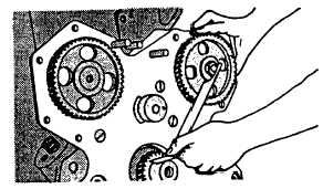
If timing gear was removed install gear. Check injection pump gear timing with JD254 timing tool. Timing
mark with "6" stamped beside it must align with center of injection pump gear, refer to FIGURE 3-111.
FIGURE 3-111. Checking Injection Pump Gear Timing
NOTE
Tighten nut to 95 ft-lbs (130 Nm).
h.
Install lockwasher (5, FIGURE 3-109) and nut (4) onto shaft.
i.
If timing gear cover was not removed install timing gear access cover.
NOTE
Tighten nuts securing pump to front plate to 20 ft-lbs (27 Nm).
j.
First pivot pump housing away from cylinder block as far as slots will allow. Then, pivot it back again, but only
far enough to align timing marks in injection pump window. This is to take up any Possible backlash.
CAUTION
When tightening fuel pressure lines at fuel injection pump, be sure not to turn fuel injection pump
fittings. Turning of these fittings may cause internal pump damage.
k.
Connect six fuel injection lines (12, 13, 14, 15, 16, and 17, FIGURE 3-59) at pump.
I.
Connect fuel tube assembly (7) to fitting (18) on fuel pump.
m.
Connect fuel supply line to fuel injection pump inlet (23).
n.
Connect throttle control system, refer to end item maintenance manual.
3-130
|
|