ARMY TM 9-2815-256-24
AIR FORCE TO 38G1-96-2
MARINE CORPS TM 2815-24/5
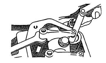
FIGURE 3-116. Checking Valve Clearance
3-32.2.
Measure Valve Lift.
Measuring valve lift can give an indication of excess wear on cam lobes, followers, and/or pushrods.
CAUTION
For a more accurate measurement, it is recommended that valve lift be measured at 0.00 inch (0.00
mm) rocker arm to-valve tip clearance.
a.
Remove valve cover, refer to paragraph 3-31.1.
b.
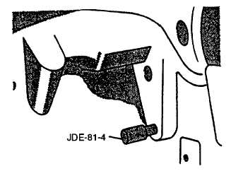
Using center bolt on harmonic balancer, rotate crankshaft clockwise and observe No. 1 pushrods. When both
pushrods can be rotated freely engine is on compression stroke. Continue to rotate engine until timing pin (JDE-
81-4) can be installed in flywheel, refer to FIGURE 3-117.
FIGURE 3-117. Installing Timing Pin
c.
Set rocker arm-to-valve tip clearance to 0.00 inch (0.00 mm) by turning adjustment nut clockwise until pushrod
cannot be turned by hand for No. 1, 3, and 5 exhaust and No. 1, 2, and 4 intake valves, refer to FIGURE 3-116.
3-141
|
|