ARMY TM 9281 5-256-24
AIR FORCE TO 38G1-96-2
MARINE CORPS TM 2815-24/5
WARNING
Compressed air used for cleaning can create airborne particles that may enter the
eyes. Pressure will not exceed 30 psig (207 kPa). Eye protection required.
(2) Use compressed air to remove all loose foreign material from cylinders and top deck.
(3) Remove cam followers from block. Wash in solvent. Lubricate with clean engine lubricating oil (MIL-L-2104)
and reinstall in the same bore from which removed.
(4) Before cylinder head is reinstalled, clean the threaded holes in cylinder block (for cylinder head capscrews)
using 1/2-13 UNC-2A tap about 4.0 inches (102 mm) long. Use compressed air to remove debris and any
fluids which may be present in the capscrew holes. Replace block if there is evidence of physical damage.
(5) Inspect top deck for flatness and serviceability, refer to paragraph 3-46.3.
e.
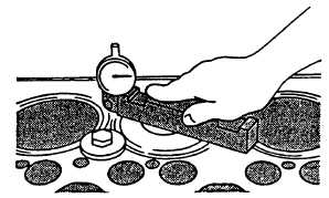
Measure cylinder liner height as follows:
(1) Bolt down liners using capscrews and flatwashers. Flatwashers should be at least 1/8 inch (3.18 mm) thick.
Tighten capscrews to 50 ft-lbs (68 Nm), refer to FIGURE 3-123.
(2) Using gage (JDG451) and dial indicator, measure liner height.
FIGURE 3-123. Measuring Cylinder Liner Height
NOTE
Variations in measurement readings can occur within one cylinder and/or
between adjacent cylinders.
(3) Measure each liner in four places, approximately at 1, 5, 7, and 11 o'clock positions as viewed from the rear
of the engine (flywheel end). Record all measurements.
(4) Liner height above block should be 0.0004 to 0.0040 inch (0.010 to 0.100 mm).
(5) Shim or replace any liner that does not meet height (standout) specification at any location. Refer to
paragraph 3-44.2. for liner replacement instructions.
(6) Maximum permissible height difference at nearest point of two adjacent liners is 0.0020 inch (0.060 mm).
(7) If liner height is less than minimum specified, one liner shim only may be installed under liner flange. Two
sizes of shims are available 0.002 inch (0.05 mm) and 0.004 inch (0.10 mm).
3-156
|
|


