ARMY TM 9-2815-256-24
AIR FORCE TO 38G1-96-2
MARINE CORPS TM 2815-24/5
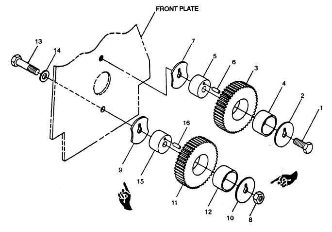
FIGURE 3-134. Idler Gears
c.
Measure sleeve bearing ID. New part ID is 1.751 to 1.753 inches (44.47 to 44.54 mm).
d.
Measure shaft OD. New part OD is 1.750 to 1.751 inches (44.44 to 44.47 mm).
e.
Oil clearance (sleeve bearing ID to shaft OD) should be 0.001 to 0.004 inch (0.02 to 0.10 mm). Maximum wear
limit is 0.006 inch (0.15 mm). If oil clearance exceeds limit, replace worn parts.
3-41.3. Installation.
a.
Install spring pins (6 and 16, FIGURE 3-134) with end of pin protruding as shown in FIGURE 3-135.
b.
Install upper thrust washer (7, FIGURE 3-134) and idler gear shaft (5) with spring pin (6) in notch. Drive shaft
into front plate until thrust washer (7) is fully seated with oil hole facing up. Tighten capscrew in engine block to
70 ft-lbs (95 Nm).
c.
Install lower thrust washer (9) and idler gear shaft (15) with spring pin (16) in notch. Drive shaft into front plate
until thrust washer (9) is fully seated with oil hole facing up. Install capscrew (13) and washer (14) through rear of
front plate and tighten capscrew to 70 ft-lbs (90 Nm).
Change 3
3-175
|
|