ARMY TM 9-2815-256-24
AIR FORCE TO 38G1-96-2
MARINE CORPS TM 2815-24/5
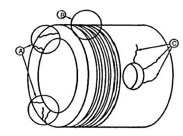
FIGURE 3-147. Piston Inspection
I.
If the original machining marks are not visible, or the piston skirt is worn to depth of original machining marks,
replace both piston and liner. If any defects are found, replace piston and liner as a matched set. If no defects
are found, proceed to next step.
m.
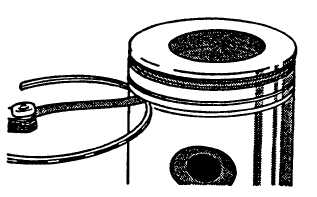
Check top ring groove using a new piston ring and feeler gage, refer to FIGURE 3-148. Ring groove clearance
must not exceed 0.008 inch (0.20 mm) when measured between top of ring and ring land. If ring groove is worn,
replace piston and liner as a matched set. If ring groove is good, proceed to next step.
FIGURE 3-148. Checking Piston Ring Groove Clearance
n.
Check second and third ring grooves using a new piston ring and a feeler gage. Ring groove clearance must not
exceed 0.008 inch (0.20 mm). Replace piston if clearance exceeds specification.
NOTE
Piston pin must be in good condition and not worn beyond specification given in step q.
o.
Dip piston pin in clean engine lubricating oil (MIL-L-2104)
p.
Install pin (6, FIGURE 3-143) through piston.
(1)
Pin should pass through piston using only light thumb pressure.
(2)
Check taper in piston pin bore by inserting pin from both sides, refer to FIGURE 3-149. If pin enters freely,
but binds in center, bore could be tapered. If bore is not tapered, insert pin to check for bore alignment.
Pin should not click or need to be forced into bore on opposite side.
3-197
|
|