ARMY TM 9-2815-256-24
AIR FORCE TO 38G1-96-2
MARINE CORPS TM 2815-24/5
CAUTION
Never use connecting rod capscrews (1, FIGURE 3-123) more than once for final engine assembly.
h.
Dip new connecting rod capscrews (1) air clean engine lubricating oil (MIL-L-2104) and install. Tighten
capscrews alternately to 41 ft-lbs (56 Nm).
i.
Torque-tum all capscrews 90 to 1 00 degrees as follows:
(1)
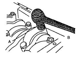
After tightening capscrews (1) to the values given above, mark connecting rod cap (A, FIGURE 3-171) and
socket.
(2)
Make a second mark on socket 90 degrees counterclockwise from first mark.
(3)
Tighten 1/4 turn (90 to 100 degrees) clockwise until mark (B) is in line with mark (A) on cap.
j.
Check engine rotation for excessive tightness as follows:
(1)
Rotate crankshaft several revolutions to be sure engine rotates without excessive tightness.
(2)
Check liners (9, FIGURE 3-143) for deep scratches which would indicate an improperly installed or broken
piston ring(s).
FIGURE 3-171. Tightening Connecting Rod Caps
(3)
Check for proper side clearance in all rods. Each rod should have slight side-to-side movement.
k.
Measure piston protrusion as follows:
NOTE
Press down on top of piston to remove oil clearances before measuring piston protrusion.
(1)
Mount a dial indicator in gage (JDG451). Place gage on top of cylinder block in such a manner that dial
indicator can be set at "zero" with top of block.
(2)
Position gage across piston with outer ends on block so dial indicator plunger can contact top of piston,
refer to FIGURE 3-172. Press down on top of gage and rotate crankshaft until piston is at TDC. Piston
height must be checked at outer most diameter of piston.
(3)
Piston protrusion should be 0.003 to 0.012 inch (0.08 to 0.30 mm) to prevent piston-to-exhaust valve
contact.
3-216
|
|