ARMY TM 9-2815-256-24
AIR FORCE TO 38G1-96-2
MARINE CORPS TM 2815-24/5
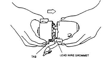
FIGURE 3-40. Installing Cover On Yoke
k.
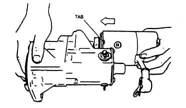
Position yoke assembly (39) on magnetic switch assembly (24) engaging tab on yoke assembly with notch in
magnetic switch, refer to FIGURE 3-41. Secure with two through bolts (7, FIGURE 3-15), new lockwashers (8),
washers (9), and new preformed packings (10). Tighten through bolts 5.1 to 8.7 ft-lbs (6.9 to 11.8 Nm).
FIGURE 3-41. Installing Yoke
I.
Connect yoke assembly lead wire (6) to terminal on magnetic switch assembly. Tighten nut to 18.1 to 26.0 ft-lbs
(24.5 to 35.3 Nm). Ensure rubber boot (37) is installed securely.
3-12.7. Installation.
NOTE
To aid in installing starter and spacer, place a 3/8 inch x 3 inches (9.52 mm x 7.62 cm) guide stud
in one of the starter mounting holes in flywheel housing.
a.
Remove cover in flywheel housing.
b.
Place spacer (4, FIGURE 3-15) and starter on flywheel housing and secure with two screws (1), new lockwashers
(2), and washers (3). Tighten screws 30 to 35 ft-lbs (41 to 47 Nm).
c.
Connect electrical leads to starter as tagged during removal.
d.
Install coolant overflow bottle and mounting plate, refer to end item maintenance manual.
Change 3
3-50
|
|