ARMY TM 9-2815-256-24
AIR FORCE TO 38G1-96-2
MARINE CORPS TM 2815-24/5
The following inspection procedure is recommended for systematic failure analysis of a suspected turbocharger failure.
This procedure will help to identify when a turbocharger has failed, and why it has failed so primary cause of failure can
be corrected. Proper diagnosis of a "non-failed" turbocharger is important for two reasons. First, identification of a "non-
failed" turbocharger will lead to further investigation and repair of the cause of a performance complaint. Second, proper
diagnosis eliminates unnecessary expense incurred when a "non-failed" turbocharger is replaced. Seven recommended
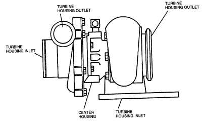
inspection steps, (refer to FIGURE 3-43) which are explained in detail in following paragraphs, are:
a. Compressor Housing Inlet and Compressor wheel.
b. Compressor Housing Outlet.
c.
Turbine Housing Inlet.
d. Turbine Housing Outlet and Turbine wheel.
e. External Center Housing and Joints.
f.
Internal Center Housing.
g. Turbo Bench Test.
NOTE
To enhance turbocharger inspection, an inspection chart (TABLE 3-3) can be used that
lists inspection steps in the proper order and shows potential failure modes for each
step. Check off each step as you complete inspection and note any problems.
FIGURE 3-43. Turbocharger Inspection Points
3-13.2.2 Compressor Housing Inlet and Compressor Wheel.
a. Check compressor inlet and compressor wheel for foreign object damage.
NOTE
Foreign object damage may be extensive or minor. In either case, the source of the foreign object
must be found and corrected to eliminate further damages.
3-53
|
|


