ARMY TM 92815-256-24
AIR FORCE TO 38G1-96-2
MARINE CORPS TM 2815-24/5
Warning
Compressed air used for cleaning can create airborne particles that may enter the eyes. Pressure
will not exceed 30 psig (207 kPa). Eye protection required.
a.
Clean all oil pump parts in solvent. Dry with compressed air.
b.
Visually inspect all oil pump components for excessive wear.
c.
Inspect pump intake tube-to-flange weld for cracks. If cracks or other defects are found, replace tube.
d.
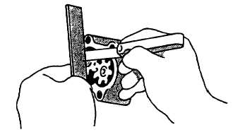
Using straight edge and feeler gage, check axial clearance between gear and pump cover, refer to FIGURE 3-
54. Clearance standard is 0.002 to 0.007 inch (0.05 to 0.017 mm). Maximum permissible axial clearance is
0.0085 inch (0.22 mm).
FIGURE 3-54. Measuring Oil Pump Axial Clearance
e.
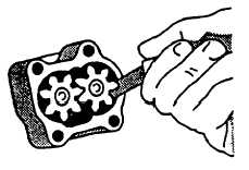
Using feeler gage, check radial clearance between gear and pump housing, refer to FIGURE 3-55. Clearance
standard is 0.004 to 0.006 inch (0.10 to 0.16 mm). Maximum permissible radial clearance is 0.008 inch (0.20
mm).
FIGURE 3-55. Measuring Oil Pump Radial Clearance
3-21.3. Installation.
a.
Install new preformed packing (11, FIGURE 3-53) in outlet tube bore in engine block.
b.
Install new preformed packing (10) on pickup tube (9) cover.
3-72
|
|