ARMY TM 9-2815-257-24
AIR FORCE TO 38G1-128-2
MARINE CORPS TM 10155A/2815-24/3
2-3
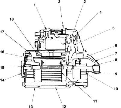
1.
Solenoid
2.
Dust Cover
3.
Dust Cover
4.
Torsion Spring
5.
Shift Lever
6.
Over-Running Clutch
7.
Gear Case
8.
Pinion Stopper
9.
Gear Case Bearing
10. Pinion
11. Armature
12. Yoke
13. Rear Cover
14. Dust Cover
15. Rear Cover Bearing
16. Brush Holder
17. Brush
18. Field Coil
Figure 2-1. Engine Starter Motor (Side View)
c. Power Stroke. The combustion of the air and fuel mixture forces the piston (8) downward, causing
the piston connecting rod to turn the crankshaft (6). The crankshaft is coupled to the end item and drives the
end item as designed.
d. Exhaust Stroke. As the crankshaft (6) turns, it pushes up on the connecting rod, forcing the piston
(8) to rise to its high point again. Once the piston begins to rise, the exhaust valve (9) opens. Exhaust gases (a
result of the air / fuel combustion) are forced out of the cylinder through the exhaust valve. The valve closes
just before the piston reaches it high point.
e. Intake Stroke. As the piston (8) moves downward again, the inlet valve (10) opens. Air is drawn
through the open valve and into the cylinder. The inlet valve closes just before the piston reaches the end of its
stroke (low point in the cylinder). The piston moves upward once more to repeat the combustion cycle.
A decompression lever (1) installed in the rocker arm cover is utilized during manual start operations.
A breather (2) regulates the amount of pressure built up on the chamber and opens to release pressure as
required. An air cleaner (3) ensure that air entering the combustion chamber is free of particles that could cause
damage to engine components.
|
|