ARMY TM 9-2815-257-24
AIR FORCE TO 38G1-128-2
MARINE CORPS TM 10155A/2815-24/3
3-20
3-15. ROCKER ARM ASSEMBLY MAINTENANCE
This task covers head cover removal, rocker arm / valve clearance adjustment, and head cover installation.
INITIAL SETUP
Tools:
Equipment Condition:
Tool Kit, General Mechanic’s Automotive
Engine cool
(Item 2, App. B, Sect. III)
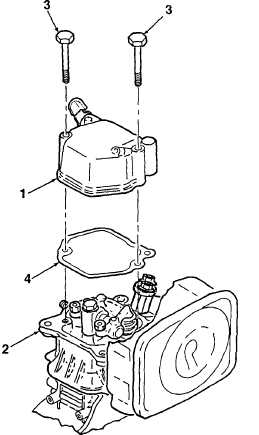
A. HEAD COVER REMOVAL.
Remove head cover (1, Figure 3-5) from cylinder
head (2) by removing bolts (3). Remove cover
gasket (4) only if replacement is required.
B. VALVE CLEARANCE ADJUSTMENT.
1.
Remove flywheel housing and recoil starter as an
assembly (Para. 3-13).
2.
Rotate flywheel in the clockwise direction until T
mark on flywheel match V mark on cylinder body
fin. This is the top dead center (TDC) position.
Intake and exhaust valves will be in closed
position.
3.
Using a feeler gauge, check rocker arm to valve
clearance (Figure 3-6). Clearance shall be 0.0039
to 0.0059 inch (0.10 to 0.15 mm). Drag on feeler
gauge when passing through gap shall be
minimal.
4.
If adjustment is required, loosen lock nut and
rotate adjusting screw clockwise / counter-
clockwise to expand / reduce gap. Tighten lock
nut and recheck clearance.
5.
Repeat steps 3 and 4 until proper clearance is
attained.
Figure 3-5. Head Cover Removal
|
|