ARMY TM 9-2815-257-24
AIR FORCE TO 38G1-128-2
MARINE CORPS TM 10155A/2815-24/3
4-7
Section IV. DIRECT SUPPORT MAINTENANCE PROCEDURES
4-7. GOVERNOR CONTROL MAINTENANCE
This task covers removal, cleaning, inspection, and installation.
INITIAL SETUP
Tools:
Equipment Condition:
Tool Kit, Master Mechanic (Item 3, App. B, Sect. III)
None
Parts/Materials:
Solvent, Dry Cleaning (Item 7, App. E)
Rag, Cleaning (Item 8, App. E)
A. REMOVAL.
CAUTION
Governor lever (7) and torque spring are
factory preset. Do not adjust locking nut or
cut lockwire.
1.
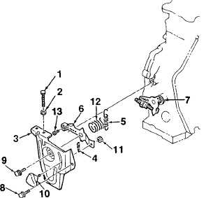
Remove adjusting screw (1, Figure 4-1) and
washer (2) from regulator bracket assembly (3).
2.
Disconnect springs (4, 5) from governor lever (7)
and manual control handle (6).
3.
Release regulator bracket assembly (3) from
cylinder block by removing screw (8).
4.
Remove screw (9), knob (10), and nut (11).
Remove screw (13) and spring (12).
Figure 4-1. Governor Control Removal
|
|


