ARMY TM 9-2815-259-24
AIR FORCE TO 38G1-125-2
MARINE CORPS 09249A/09246A-24
5-13
(27) Remove thrust sleeve (49, Figure 5-1), thrust washer (50), and governor weights (51).
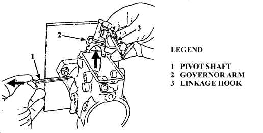
(28) Remove pivot shaft nut (52) and O-ring seal (53) from one side of pivot shaft (54).
(29) Remove pivot shaft (54), governor arm (55), and linkage hook (56), refer to Figure 5-9.
FIGURE 5-9. GOVERNOR ARM AND LINKAGE HOOK REMOVAL
(30) Remove retaining ring (58, Figure 5-1) using snap ring pliers (20044). Remove thrust spring (59)
and thrust washer (60). Remove thrust bearing (61) using snap ring pliers (20043).
CAUTION
Drive shaft is easily damaged. Handle drive shaft with care. Failure to
comply could result in damage to fuel injection pump.
(31) Remove drive shaft (62), drive shaft nut (63), lock washer (64), and Woodruff key (65).
(32) Remove screw (66) and gasket (67). Discard gasket.
(33) Position fuel injection pump housing (1) with flange facing upwards. Remove drive shaft bearing
(68), oil side seal (69), spacer (70) and fuel side seal (71) using Bearing and Seal Puller (28311),
refer to Figure 5-10. Discard drive shaft bearing, oil side seal, and fuel side seal.
(34) Remove transfer pump end cap (72, Figure 5-1), inlet filter screen (73), and transfer pump
regulator assembly (74).
(35) Remove adjusting screw (75), regulating spring (76), regulator piston (77), sleeve seal (78), and
regulator assembly roll pin (79). Discard sleeve seal.
(36) Remove transfer pump liner (80), transfer pump blades (81), and transfer pump blade springs (82).
(37) Remove liner locating ring (83) and rotor retainers (84).
|
|