ARMY TM 9-2815-259-24
AIR FORCE TO 38G1-125-2
MARINE CORPS 09249A/09246A-24
5-40
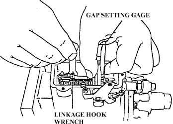
(59) Ensure the governor linkage gap is properly set up prior to calibration by performing the
following:
(a)
Partially loosen the adjusting screw with (13379) wrench until the parts can move in
relationship to one another but with some resistance.
(b)
Expand the linkage to the maximum gap. Refer to Figure 5-53. Insert thickness gap setting
gage between the throttle shaft and the upright on the linkage hook. Refer to Stanadyne
Service Bulletin 95.
(c)
While holding the throttle lever in the wide open throttle position, close the gap to the
thickness of the gage, press the linkage hook upright flush against the gage and tighten the
linkage hook locking screw.
(d)
Rotate the drive shaft 1/2 turn and recheck the gap to ensure it is within the specified
tolerance.
FIGURE 5-53. SETTING GOVERNOR LINKAGE GAP
(60) Invert pump in vise. Install new seal to head locating screw and install head locating screw to
pump finger tight.
|
|