ARMY TM 9-2815-259-24
AIR FORCE TO 38G1-125-2
MARINE CORPS 09249A/09246A-24
5-56
d. Installation.
(1)
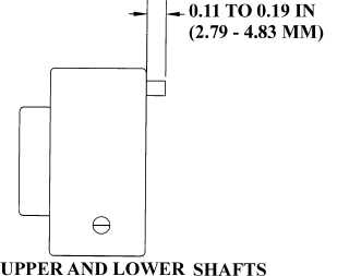
Install spring pins (6 and 16, Figure 5-63) with end pin protruding as shown in Figure 5-64.
(2)
Install upper thrust washer (7, Figure 5-63) and idler gear shaft (5) with spring pin (6) in notch.
Drive shaft into front plate until thrust washer (7) is fully seated with oil hole facing up. Tighten
capscrew (1) in engine block to 59 lb-ft (80 Nm).
(3)
Install lower thrust washer (17) and idler gear shaft (15) with spring pin (16) in notch. Drive shaft
into front plate until thrust washer (17) is fully seated with oil hole facing up. Install capscrew (13)
and washer (14) through rear of front plate and tighten to 59 lb-ft (80 Nm).
(4)
If sleeve bushings (4 and 12) were removed, use an arbor press driver and handle to install sleeve
bushing (4) in idler gear (3) and sleeve bushing (12) in idler gear (11).
(5)
Install lower idler gear (11), thrust washer (10), washer (9) and nut (8).
(6)
Time camshaft and install upper idler gear (3), thrust washer (2) and capscrew (1). Refer to
paragraph 5.4.1.
(7)
Install oil pan, refer to paragraph 4.5.3.
(8)
Install timing gear cover, refer to paragraph 4.9.2.
FIGURE 5-64. SPRING PIN PROTRUSION
|
|