ARMY TM 9-2815-259-24
AIR FORCE TO 38G1-125-2
MARINE CORPS 09249A/09246A-24
5-86
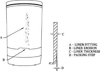
FIGURE 5-78. INSPECTING CYLINDER LINER PITTING
(g)
Inspect cylinder block for cracks or erosion in the o-ring packing areas. Replace cylinder
block, refer to paragraph 5.4.8, if cracks or erosion are observed.
(h)
Calculate piston-to-liner clearance as shown below. Replace piston and cylinder liner if any
clearances exceed specifications.
1
Position piston (4, Figure 5-72) without rings in matched cylinder liner with piston
front and cylinder liner front aligned. Move piston down until bottom edge of piston
skirt is 1.00 in. (25.4 mm) from bottom of cylinder liner.
2
Use feeler gauge to measure piston skirt-to-cylinder liner clearance 90 degrees (1/4
turn) away from piston pin bore. Record measured clearance. Compare piston skirt-
to-cylinder liner clearance with specifications given in Table 5-11.
3
Turn piston 90 degrees (1/4 turn) in liner. Measure piston skirt-to-cylinder liner
clearance 90 degrees (1/4 turn) away from piston pin bore. Record measured
clearance.
4
Remove piston from cylinder liner, turn piston upside down, and position piston
upside down in cylinder liner with piston “front” and cylinder liner “front” aligned.
5
Position piston so bottom edge of piston skirt is 1.00 in. (25.4 mm) below top of
liner.
|
|