ARMY TM 9-2815-260-24
AIR FORCE TO 38G1-126-2
MARINE CORPS TM 09244A/09245A-24
4-66
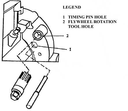
FIGURE 4-46. ENGINE TIMING HOLE LOCATION
(f)
Check rocker arms on Number 1 cylinder, refer to Figure 4-47. If both rocker arms are
loose, the engine is set with No. 1 Piston at TDC. If both rocker arms are not loose,
engine is one full revolution (360°) away from TDC, rotate engine slightly and repeat
steps c and d.
(2) Set Engine with No. 6 Piston at TDC Compression Stroke.
NOTE
Setting engine with No. 6 Piston at TDC Compression stroke is required in
many different maintenance steps and is not a stand alone maintenance
procedure.
(a)
Remove rocker arm cover, refer to paragraph 4.7.1.
(b)
Remove cover plate from timing hole (1, Figure 4-46).
(c)
Position timing pin (JDE81-4) in timing hole (1, Figure 4-46).
(d)
Position flywheel rotation tool (JDG820) in hole (2) and insure that tool meshes with
flywheel gear.
|
|