ARMY TM 9-2815-260-24
AIR FORCE TO 38G1-126-2
MARINE CORPS TM 09244A/09245A-24
5-38
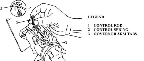
NOTE
Ensure that cross loop on end of control spring is installed between tabs on
governor arm.
(52)
Depress metering valve arm (43, Figure 5-1) and install control rod (1, Figure 5-49). Install
control spring (2) over governor arm tabs (3).
FIGURE 5-49. CONTROL ROD INSTALLATION.
(53)
Depress metering valve arm (43, Figure 5-1) and install seal washer (17) and control rod guide
(16). Torque control rod guide to 70 to 80 lb-in. (8 to 9 Nm).
(54)
Install spring pin (15), O-ring (14), and slotted adjusting cap assembly (13).
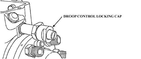
(55)
Install droop control locking cap (Figure 5-50).
FIGURE 5-50. DROOP CONTROL LOCKING CAP INSTALLATION.
|
|