TM 9-2920-243-34
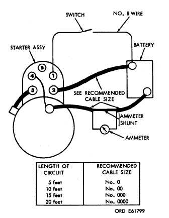
Figure 3-44. Starter test setup.
b. Close switch and measure current draw and
maximum and armature speed should be 6500
rpm minimum.
c.
If a low speed and high current condition
exists, check armature for excessive arcing,
grounds, and shorts. Also examine starter for
armature drag. If drag exists, check for loose pole
shoe screws and tighten as necessary; or,
disassemble starter and check for armature ec–
centricity or faulty bearings.
d.
If low speed and low current condition exist,
inspect starter for faulty connections and for poor
brush contact.
3-28. DELETED.
3-29. Waterproof Test
a.
Place waterproof adapter over pinion
housing. Install adapter and apply 6 psi air
pressure.
b. Allow pressure to build up and then submerge
starter in a suitable water tank.
c. Check for air leaks evidenced by bubbles. No
leakage is permitted.
d.
If leaks are present, disassemble starter,
install new packings and gaskets. Coat packings
and gasket with grease before installation and apply
sealer to all external screws and pipe plugs. Assemble
armature speed. Current draw should be 50 amps
starter and retest for leaks.
Section V. REPAIR STANDARDS
3-30. General
approved for service.
An asterisk (*) in the “Wear
limits” column should be replaced when worn
The repair standards listed in paragraph 3–31 give
beyond limits given in “Sizes and fits of new parts”
maximum, minimum, and key clearances of new or
column. In “Sizes and fits of new parts” column, “L”
rebuilt parts. They also give wear limits, which indicate
indicates a loose fit and “T” indicates a tight fit. All
the point to which a part or parts may be worn before
dimensions are given in inches unless otherwise
replacement, for maximum service with minimum
specified.
replacement. Normally, all parts which have not
3-31. Wear Limits
been worn beyond dimensions shown in “Wear
limits” column or damaged from corrosion will be
All reference letters are keyed to figure B-2.
3-20 Change 1
|
|


