
| Tweet |

Custom Search
|
|

|
||
 3161 GOVERNOR
SYSTEMS OPERATION
As control air pressure enters the speed setting
bellows through the inlet port, expansion of the bellows
takes place. The bellows pushes down on the speed
setting lever to the left of the pivot. This lifts the right end
of the speed setting lever against the feedback spring
force to close the nozzle to drain.
Supply oil flows through an orifice to the lower
side of the speed setting pilot valve plunger and then to
drain through the nozzle. When oil flow from the nozzle
is stopped by the speed setting lever, oil pressure
increases and the speed setting pilot valve plunger
moves up. This lets control oil go to the top of the speed
setting piston. As the control oil pressure increases, the
speed setting piston moves down to increase the
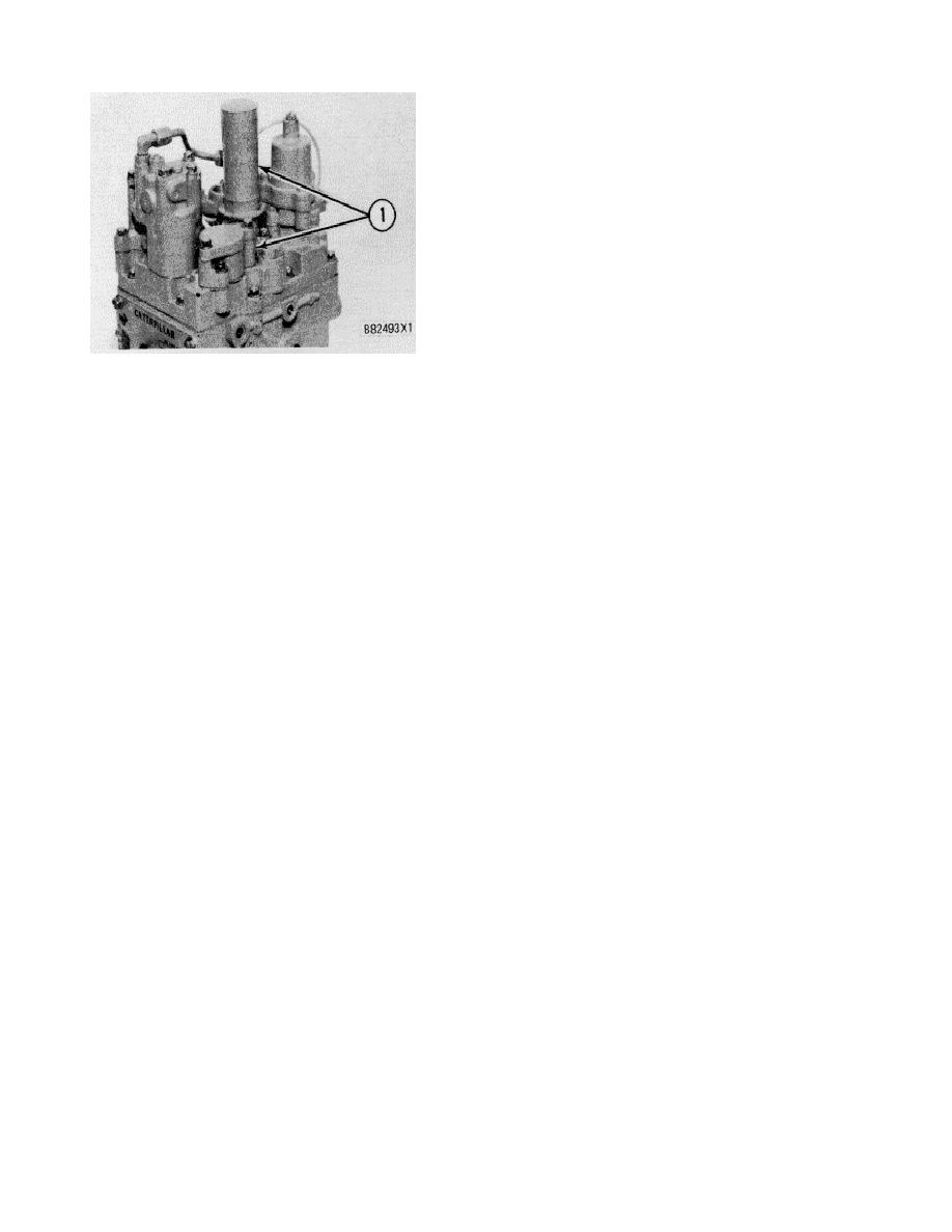
ELECTRIC SHUTDOWN
governor speed setting through a rod and lever
1. Electric shutdown assembly.
connected to the governor speed setting shaft.
There is a diode used in the circuit for the
As the speed setting piston moves down, the
electric solenoid because it is polarity sensitive. If the
feedback spring is put under compression and pushes
wires are connected the wrong way the solenoid will not
the speed setting lever away from the nozzle. Control oil
operate.
can now go to drain and the pilot valve loading spring
pushes the pilot valve plunger down to stop oil flow to the
The electric shutdown can be used by itself, or in
top of the speed setting piston. This results in the speed
addition to the manual and pressure shutdown controls.
setting piston stopped in a new position that is
If this shutdown is added after the governor has been
proportional to the air pressure supplied to the speed
shipped from the factory, an adjustment must be made.
setting bellows.
See TESTING AND ADJUSTING section for the correct
adjustment.
Decrease Engine Speed
When the electric shutoff is used by itself, a
When the control air pressure is lowered, the
small cover and gasket must be installed on top of the
speed setting bellows moves back toward its original
shutdown assembly.
position. The feedback spring now pushes the speed
setting lever away from the nozzle and control oil goes to
drain through the nozzle.
PNEUMATIC SPEED SETTING CONTROL
As control oil pressure goes to drain, the oil
The pneumatic speed setting control is installed
pressure below the speed setting pilot valve plunger is
on the left front corner of the governor top cover.
decreased and the pilot valve loading spring moves the
Because of its design, it is not practical to add the
plunger down. This lets control oil above the speed
pneumatic speed control on the 3161 Governor in the
setting piston go to drain and the feedback spring
field.
pushes the piston up. When the piston moves up, the
force on the governor speed setting lever is lowered and
System air pressure from a remote throttle and
the governor speed setting is reduced.
internal pressure oil from the governor operate the
control to increase or decrease the speed at which the
The speed setting piston moves up until the
engine runs. This control has the ability to repeat
force of the feedback spring and the speed setting
constant speed settings over a large range of conditions.
bellows moves the speed setting lever to close control oil
to drain at the nozzle. At this time, the speed setting pilot
The pneumatic speed setting control has a
valve plunger moves up to stop control oil movement
standard air pressure range of 70 to 415 k Pa ( 10 to 60
above the speed setting piston. This results in the speed
psi). Special applications of this control can use a
setting piston stopped in a new position that is
pressure range of 35 to 380 kPa (5 to 55 psi) or 35 to
proportional to the air pressure applied to the speed
620 kPa (5 to 90 psi).
setting bellows.
Increase Engine Speed
165
|
||
|
||


