PAR 2 2 6 - 2 2 7
A S S E M B LY
CHAP 5, SEC XX XIII
226. ASSEMBLY
Note. Press o n the extreme outer
——
diameter of seal 46 when installing
~. Left-output Shaft Assembly
into retainer 41. Install packing 45,
—.>
seal 46, spacer 44 amd retainer 4:1 as
(1) Install preformed packing 45 (fig.
a unit onto oc tjjut shaft assembly 47.
385, fold-o~t 14) into spacer 44.
(4) Install roller bearing 39 clnto shaft
assembly 47, pressing the bearing until it is
( 2 ) Using an oil S e a 1 feplacer and a flrml~ ;Seated.
press, install the seal onto the output shaft
spacer (fig. 239).
Q. Right-output Shaft Assemt~. The
left- and-right-o~t=~~~ ssernblies a r e
(3) Install preformed packing 45 (fig.
ickmtical, therefore the assembly procedure
385, fold-out 14) and spacer 44 with seal 46
is the same as described in ~(l) thrc)ugh 2(4),
into retainer 41.
above.
#c4?
Section XXXIII. ASSEMBLY OF POWER TRAIN FROM SUBASSEMBLIES
227. ASSEMBLY STEPS –
MAIN TRANSMISSION ASSEMBLY
—
&—
Note. The following assembly steps
for the XTG-411 -2A power train are
to be used in the same manner as the
disassembly steps, Refer to par, 73~
and b.
—
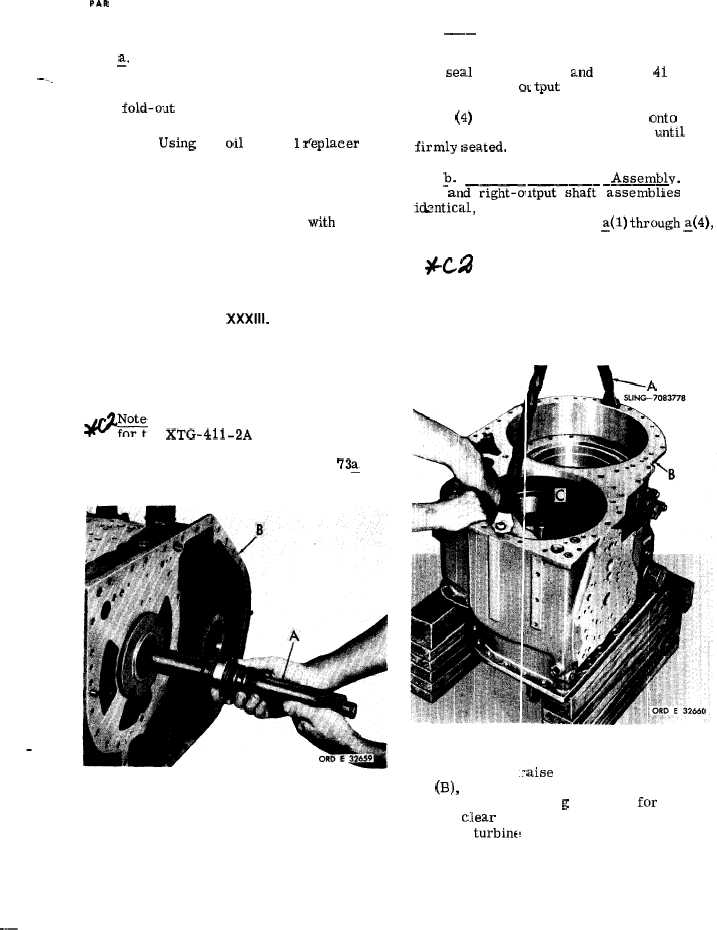
Figure 240 (Step 1)
Install turbine shaft assembly (A) into main
transmission housing (B).
Figure 241 (Step 2)
Using sling (A), .:aise the transmission hous-
ing (B:), holding onto the turbine shaft (C).
Block t h e housing h i g h enough fcu’ turbine
shaft to clear the assembly table. Then block
under the turbinf shaft.
163
.——
|
|