*C2
C H A P 5, SEC X X X I II
A S S E M B LY
P A R 2 2 7 , S T E P S 7 5 - 7 8
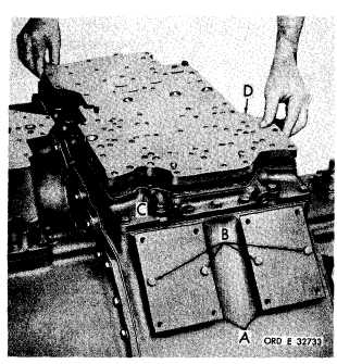
Figure 314 (Step 75)
Install brake inspection covers (A) and tempo-
r a r i l y r e t a i n w i t h f o u r 3 / 8 - 1 6 x 1 - 1 / 8 b o l ts
(B). Install oil transfer plate assembly gasket
(C) and plate assembly (D).
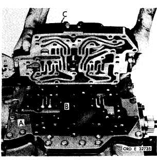
Figure 316 (Step 77)
Install relay valve body assembly gasket (A)
a n d t w o n y l o n b a l l s ( B ) . I n s t a l l v a l v e b o dy
a s s e m b l y ( C ).
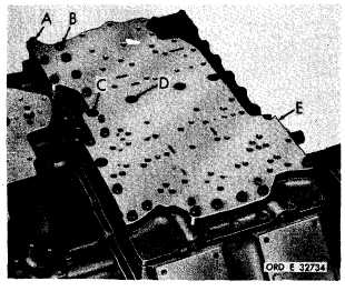
Figure 315 (Step 76)
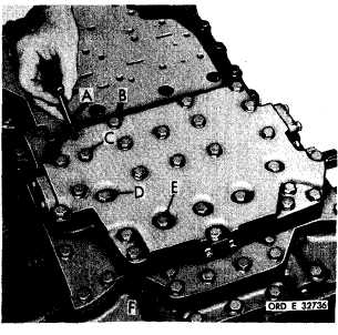
Figure 317 (Step 78)
I n s t a l l e i g h t 3 / 8 - 1 6 x 3 ( A ) , n i n e 3 / 8 - 1 6 x
Install nine 3/8-16 x 3-1/4 (A), five 3/8-16 x
1 - 5 / 8 ( B ) , t w o 3 / 8 - 1 6 x 1 - 1 / 8 ( C ) a n d f o ur
4-1/2 (B), one 3/8-16 x 2-1/2 (C), nine 3/8-16
3/8-16 x 2-1/2 bolts (D) with lock washers to
x 2-3/4-inch (D) and four 3/8-16 x 4 bolts (E)
retain oil transfer plate assembly (E). Using
with lock washers to retain relay valve body
a 9/16-inch wrench, torque all bolts to 26-32
a s s e m b l y ( F ) . U s i n g a 9 / 1 6 - i n c h w r e n c h,
p o u n d - f e e t .
torque bolts to 26-32 pound-feet.
1 8 2
|
|