P A R 2 2 7 , S T E P S 7 9 - 8 2
A S S E M B LY
C H A P 5, SEC X X X I II
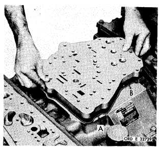
Figure 318 (Step 79)
I n s t a l l s t e e r v a l ve
and body assembly
b o d y a s s e m b l y g a s k e t ( A)
(B).
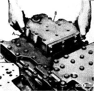
Figure 319 (Step 80)
I n s t a l l o n e 3 / 8 - 1 6 x 4 - 3 / 4 ( A ) , o n e 3 / 8 - 1 6 x
4 - 1 / 4 ( B ) a n d t h i r t e e n 3 / 8 - 1 6 x 3 - 1 / 2 b o l ts
( C ) w i t h l o c k w a s h e r s t o r e t a i n s t e e r v a l ve
body assembly (D). Using a 9/16-inch wrench,
torque bolts to 26-32 pound-feet.
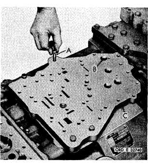
Figure 320 (Step 81)
Install oil transfer plate assembly gasket (A)
and plate assembly (B).
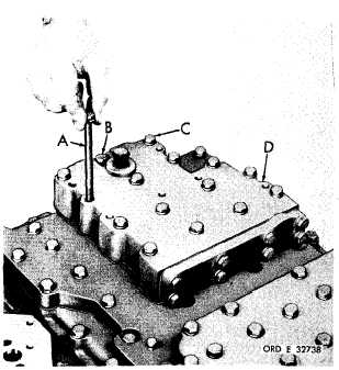
Figure 321 (Step 82)
Install four 5/16-18 x 1-1/2 bolts (A) with lock
w a s h e r s a n d f o u r 5 / 1 6 - 1 8 x 1 - 1 / 8 b o l t s ( B )
with flat washers to retain oil transfer plate
a s s e m b l y ( C ) . U s i n g a 1 / 2 - i n c h w r e n c h ,
torque bolts (A) to 13-16 pound-feet and bolts
(B) to 17-20 pound-feet.
1 8 3
|
|