C H A P 5, SEC X X X I II
A S S E M B LY
P A R 2 2 7 , S T E P S 8 3 - 8 6
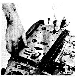
Figure 322 (Step 83)
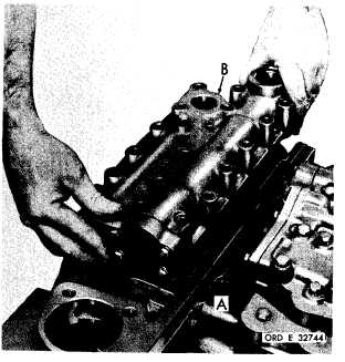
Figure 324 (Step 85)
Install main control valve body assembly gas-
ket (A) and body assembly (B).
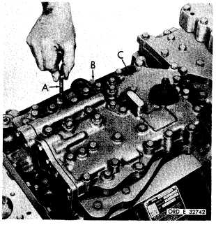
Figure 323 (Step 84)
Install six 5/16-18 x 2-1/2 (A) and twenty-two
5/16-18
x
2-1/4-inch
bolts
(B)
with
lock
wash-
ers to retain main control valve body assembly
( C ) . U s i n g a 1 / 2 - i n c h w r e n c h , t o r q u e b o l ts
to 13-16 pound-feet.
I n s t a l l l o c k u p s h i f t a n d p r e s s u r e r e g u l a t or
valve body oil transfer plate gasket (A) and
plate (B).
Figure 325 (Step 86)
I n s t a l l l o c k u p s h i f t a n d p r e s s u r e r e g u l a t or
valve body assembly gasket (A) and body as-
s e m b l y ( B ) .
1 8 4
|
|