TM9-2815-202=34
8-7. FUEL INJECTOR CONTROL LEVER ADJUSTMENT (Cent)
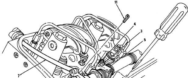
j. Tightenadjustingscrew(4)l/8turn. Hold adjusting screw and tighten locknut (3).
l
k.
1.
m
n.
o.
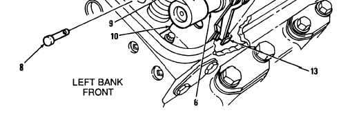
Check clevis pin (8). Pin must turn
position.
If clevis pin (8) fails to rotate freely
again.
freely in control tube lever (9) when 1 L is in FULL FUEL
in control tube lever (9), adjust injector control rack lever (5)
Check injector control rack lever adjustments. Hold speed control lever (12) in maximum engine
speed position. Using a screw driver, press downward on injector control rack (13); then slide
screw driver off from injector control rack. Control rack should spring back upward.
If injector control rack(13) does not spring back, loosen adjusting screw locknut (3) and tighten
adjusting screw (4) slightly. Tighten locknut. Check adjustment using steps h and i.
Move governor speed control lever (12) to maximum engine speed position. If injector control rack
(13) becomes tight before governor speed control lever reaches end of travel, setting is to tight.
Loosen locknut (3) and turn screw (4) slightly counterclockwise. Tighten locknut. Check setting
using steps i thru j.
Connect right bank throttle control rod (7) to control tube lever (9) using clevis pin (8) and cotter
pin (1 1).
Adjust 1 R injector rack control lever as outlined in steps e thru k.
8-18
|
|